SCADA remains relevant for industrial automation

Embedded workflow, engineering model support, and auto-discoverable assets are among the technologies keeping SCADA alive.

Figure 1: Supervisory control and data acquisition (SCADA) increases operator efficiency. In the Enerchem facility, use of modern SCADA means that data is accessible and all needed functionality is found in a single system. Courtesy: Kymera Systems
Placing computer power onto “edge devices” as near to production as possible is a goal hotly pursued in today’s industrial automation circles. What’s more, in just the past few years, copious amounts of process and operations data moved to the cloud.
Yet these developments by no means obviate the role of supervisory control and data acquisition (SCADA) systems as a convenient and secure aggregation point. SCADA instances are found across the oil and gas industries and in all major production industries. In fact, smart instrumentation and cloud modalities make SCADA more relevant to the entire business enterprise.
“One basic difference in today’s oil and gas environment is that it is expected that operations data can be accessed from the corporate office,” says Doug Rauenzahn, a product director.
 

SCADA installation

A SCADA installation typically includes computer workstations, programmable logic controllers (PLCs), and other instrumentation for system inputs and outputs (I/O). Unlike a distributed control system (DCS), SCADA control functions may be limited. The feedback loop passes through the PLC, while SCADA monitors loop performance. That is, PLCs assume parameter control, while operators monitor results and, for example, change set points. Peer-to-peer communications among the controllers may be lacking.
The more modern programmable automation controller (PAC) addresses these concerns to compete with a DCS as a control paradigm.
Another element of a SCADA installation is a distributed database and tag- or point-data elements. Each tag represents a single system input or output value. Examined in series, these value-time stamp pairs track point history. Metadata may also be stored with tags. Systems with many thousands of tags are common today.
SCADA includes tools for process design and development. Of prime importance is the ability to efficiently implement multiple instances of a system. SCADA implementations often include pre-integrated data historians and portal connectivity to aggregate data and communicate results, analytics, etc., to interested parties.
To deal with the complexity of it all, modern SCADA uses object-oriented programming to define virtual representations of each particular entity mirrored in the graphical interface. These virtual objects included address mapping of the represented node and other valuable information. Virtual objects also play a role in supporting SCADA’s ease of implementation since they are available for reuse in multi-plant scenarios.
Object orientation opens a wealth of possibilities. “The object model created in SCADA is an abstraction that can be used by other systems aimed at analytics and optimizations and to feed first-principle engineering or other type models,” says Andy Weatherhead, manager of global engineering.
SCADA increasingly incorporates the Industrial Internet of Things (IIoT) technology. Smart instrumentation and cloud technologies lead to more complex control algorithms, while open network protocols improve SCADA cybersecurity.
 

Upstream SCADA territory

As previously mentioned, SCADA is used extensively in industries including energy and power, water and wastewater, manufacturing, and refining. In the oil and gas industries, sub-sea level drilling and production control are typically the purview of DCS, although SCADA implementations tend to proliferate as a means to roles, based on collaboration or cross-functional operations.
According to Darren Schultz, director, of SCADA, oil, gas, and chemicals, in today’s North American upstream gas markets, the gas, well, or pad is typically PLC-controlled, as are the gathering systems connecting the pads, including the compressors involved. On the other hand, gas processing facilities, transmission gas lines, and gas delivery typically are under an independent DCS, and SCADA is widely applied in pipeline and distribution networks.
“Oil production is similar in that field operations are most often addressed with SCADA, refining with DCS, and pipelines are again SCADA-equipped. In the oil industry, you also have tank farms, which may be managed using DCS from nearby processing plants,” says Schultz.
Actual control requirements differ by well type. For natural-flow wells, casing pressure, temperature, and flowing-valve position are monitored, while gas wells further rely on compensated flow calculations. Remote control is limited to the shutdown valve on a natural-flow well. For an artificial-lift well, motors or gas lift valves are also controlled.
Compressor stations in a pipeline system maintain pressure for gas delivery to destination. A gas pipeline typically has multiple compressor stations. A gas or liquid pipeline has block or segmenting valves that can shut down pipeline segments. Valued information includes pressure, temperature, flow, and valve position. Pump stations maintain system pressure or match flow demand. Multiple pump stations connect to the pipeline, with connectivity back to a central location.
Figure 2: Enerchem International, a producer and distributor of hydrocarbon drilling and fracturing fluids, uses fractionation to treat crude, unprocessed oil. With just more than 30,000 tags, the facility recently updated its SCADA to take advantage of b
 

Beyond supervision and control

“What’s exciting about the upstream today is the great uses it has for cloud computing and for something that is happening right now, the advent of auto-discoverable assets technology,” says Weatherhead.
Use of auto-discovery will significantly ease the pain of field implementations. “The cloud offers a ready-made infrastructure for SCADA,” says Weatherhead. “Combined with a services approach, an operator can have power, use a wizard to set up, and be processing data in 5 minutes. Unfortunately, today, in too many cases, you see sites where despite using the very latest drilling technologies, after 3 months of work, they still haven’t tied into SCADA. Three months of lost optimizations is real money.”
Another interesting element to SCADA to petroleum industry efforts aimed at best practices actually has been available for some time. “Over the last several years I’ve found intense interest in the subject of workflows in upstream oil and gas,” says Weatherhead.
Workflows are the traditional discipline of industrial engineers or operations management specialists, types not typically found at wellsites. But workflow isn’t something applied exclusively in offices and factories. A defined process and defined work flow are important benefits for an upstream sector with operations that employ multiple 3rd party-specialist suppliers.
“What [are] wanted are workflows for such things as ‘take a well test’,” says Weatherhead. “It sounds simple, but if you don’t have the different systems involved well-test integrated, you can’t create a relevant workflow. Again, an object data model as found in SCADA provides a level of abstraction that allows easy linkages, much as a bus where elements use device drivers to plug in.”
According to Technical Toolboxes, an industry software provider, when thinking about SCADA implementations, one way to segment upstream operations is pertaining to a) reservoir, b) completion, and c) production. Once the requirements of each are defined by means of production workflows, improvements can be made. Cross-functional objectives can be addressed as role-based goals for “reservoir surveillance, well-test validation, and production optimization.”
With a Web browser, all interested parties-and no malicious parties-access a reliable, single source of truth. It’s the availability of a relevant, configurable interface that can kick off an evolution in how things work.
What’s more, “Web-based interfaces provide a self-service environment so resources aren’t wasted laboriously building or modifying screens. Users quickly become adept at building them and the dashboards that serve their needs. That being said, hesitations persist about using Web interfaces in a control network, as opposed to a business network,” says Rauenzahn.
 

IT-based automation strategies for the oil and gas industry

Rauenzahn says a more strategic approach to IT-based automation use in oil and gas industries will involve collecting data and managing operation in a way that approaches closed-loop control. “SCADA can furnish data to first-principle physics and other type models extensively used in the upstream. Model output is in turn used to tune predictive analytics models, which allow operators to see a well’s probable future direction. This is the advent, or at least contributes to, the ability of the oil and gas industry to achieve the kind of closed-loop control familiar in plant-based processes,” says Rauenzahn.
Weatherhead agrees. “Upstream production is not a closed-loop process, but that’s where the industry is headed. It will come, and it’s not so far away.”
At the end of day, Rauenzahn concludes, “You have to take a holistic approach to justifying automation expense in oil and gas. You have silos of data and silos of people. You have to look at the costs of poor coordination. When you can build workflows to reflect actual processes you can build a culture that encourages the information sharing [and] that leads to productivity growth.”
 
Kevin Parker is a senior contributing editor to Oil & Gas Engineering magazine.
Industrial Control Links (ICL) products can be found at AndersonControl.com here

Inductive Factor 1 Sensors

sensorConstant distance towards any metal

Inductive Factor 1 sensors offer the great benefit of maintaining the same sensing distance towards all metals. Unlike standard sensors where this value changes, depending on the material. The benefits of Factor 1 sensors are obvious: This uniform distance offers outstanding flexibility in system conception and sensor installation. Contrary to conventional sensors, Factor 1 sensors feature enhanced sensing distance towards many different metals. Hence, they are even perfect for applications with variable objects.
Your benefit:

  • Utmost flexibility in construction and installation „
  • Uniform, large sensing distance towards any metal „
  • Shorter installation times, thanks to minimal adaptation effort „
  • Eased alignment thanks to large sensing distance „
  • Reduced sensor variety – the same sensor will match different applications

 
factor1
fast sense

Encoders For Medical Imaging


groupshot-w-trydynaparThanks to advancements in medical imaging technology in recent decades, doctors are now able to capture in seconds what used to take hours for diagnosis.
MRI is a noninvasive diagnostic technique that uses nuclear magnetic resonance to produce cross-sectional images of organs and other internal body structures. Dynapar offers a range of industry duty encoders designed to comply with FDA manufacturing guidelines for MRIs and X-Ray imaging. In x-Ray machines our encoders move water in and out of the machine, while in CT Scan and MRI machines they move patients in and out and measure the rotating speed.
Spacer

Recommended Solutions

H20 Hubshaft Encoder Try Dynapar

H20 Hubshaft

The H20, economical in size is the solution for your medical imaging application. It provides a wide range of resolutions along with a hubshaft with spring tether for easy installation.


AI25devicenet-Large

AI25 Absolute Encoder

Precise positioning and onboard diagnostics make the AI25 absolute encoder an ideal fit for your medical imaging application. Single turn and multi turn capabilities allow for the critical feedback required in medical imaging devices.

Different Types and Applications Of Totalizing Counters

Totalizers are counters that “total” the number of cycles applied to their inputs. The totalizing function does not provide control outputs or preset limits, although some of our multi-function products have the totalizing capability as well as output and control functions. They may be a mechanical counter, electromechanical counter or an electronic counter, all of which may be resettable or non-resettable.

Mechanical Counters

Mechanical totalizing counters typically use printed wheels or drums to display the count value and are actuated by an external force on a lever or shaft in a reciprocating or rotating action. Mechanical totalizing counters are very robust in their construction and are often found in severe environments which could destroy other types of counters.

Applicationfabric_machine

A mechanical totalizing counter can be used as a yardage counter for sheet goods, fabric, upholstery, etc. in a factory or commercial setting.

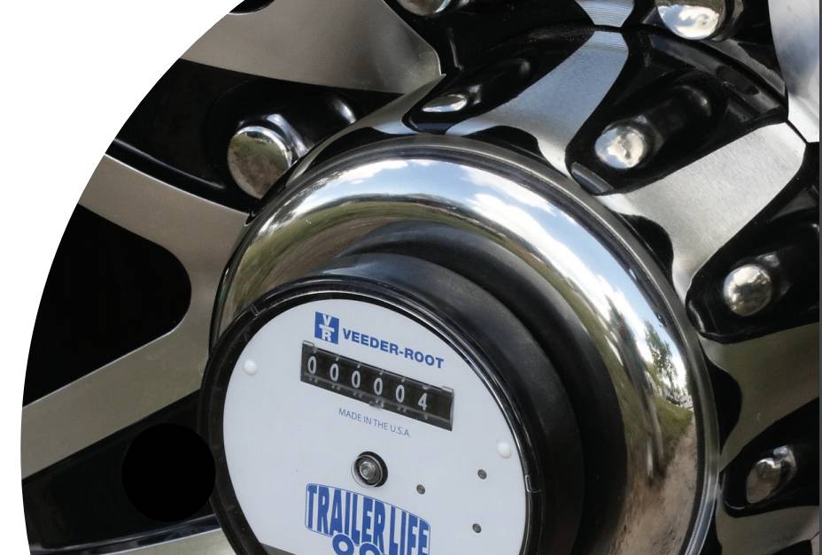
Typical Veeder-Root Counter

743415-005 Worm Drive is part of the 7234 series and pairs well with 15537-070  Measuring Wheels.

Electromechanical Counters

Electromechanical totalizing counters generally are operated by an electrical pulse from a switch or relay and increment counts as the pulses are applied. Certain models have counting coils designed as “continuous duty” which means that the voltage applied to the counter may be of extended length or continuous without causing damage to the coil. They are typically panel-mounted or base-mounted and offer a low to mid-range cost solution for numerous applications.

Applicationpinball

An electromechanical totalizing counter can be used to count cycles in a gaming machine.

Typical Veeder-Root Counter

779086-006 is part of the 7790/7791 Series. This series of economical miniature totalizers is available in all popular mounts and operating voltages.

Electronic Counters

Electronic totalizing counters are almost always panel-mounted and generally have a good degree of environmental protection making them suitable for wet, damp, or dusty locations. They may be self-powered by an internal battery or externally powered, and are designed to accept a wide range of count inputs like dry contact closures, voltage pulses, TTL level inputs, and quadrature inputs from incremental encoders. Some models offer scalable inputs, meaning that the number of input pulses can be scaled as they come in to result in a readout of more meaningful units of measurement, often referred to as engineering units.

Application

An electronic totalizing counter can be used as a maintenance or usage counter (for revenue) in a copier machine.

Typical Veeder-Root Counter

C342-0462 is one counter in the C342 Totalizing Counter series. This series provides ultra-compact 1/32 DIN totalizers available with LCD or LED display and AC/DC inputs.
Totalizing counters, in all their various types, is an important component in a myriad of applications. So, choose Veeder-Root totalizing counters for a totally reliable, durable, and accurate solution!

by Phillip Warwick – Eagle Signal / Veeder-Root


POPULAR DOWNLOADS

1667, 1669 Series Visicounter

PDF, 392.61 KB

7999 MITE Series Totalizer

PDF, 351.85 KB

A103 Series Preset Counter

PDF, 476.78 KB

C346 Series Multifunction Counter

PDF, 474.90 KB

C628 Series Totalizer

PDF, 356.64 KB

Zone 1 Hazardous Area Rated Incremental Encoders

560x300-EN-Series-Header.png

Zone 1 Hazardous Area Rated Incremental Encoders

The new EN42 hollow-shaft and EN44 hub-shaft incremental encoders eliminate the cost, guess work and hassle of installing a barrier thanks to encapsulated electronics. The EN series offers ATEX, CSA and IECEx triple certification and a powerful signal driver for universal use in oil & gas equipment applications.
 

en-series-atex-csa-iecex-certsATEX, CSA, IECEx Triple Certified

With enforcement of regional certifications on the rise, the EN series is a flexible solution for zone 1 use with ATEX, CSA and IECEx certifications. The EN series also offers the industry’s leading operating temperature range of -50° to 100° C.

RT8-sine-scope-line-driver

High Power Line Driver Available

The EN series offers a high power mosfet line driver (10-30 VDC) is for applications requiring a long cable run to ensure reliable signal output without sacrificing performance.

en-series-wiringEasy to Install with No I.S. Barrier Needed

Both the EN42 and EN44 offer encapsulated electronics with increased safety interface for zone 1 use eliminating the need for a separate I.S. barrier and the guesswork to install one. The EN44 also offers a standard B100 mounting flange and integrated double helix coupling for easy installation.

EN42 Hollowshaft

en42-large

EN44 Hubshaft

en44

1 to 5,000 PPR 1024 or 2,048 PPR
Hollow Shaft Hubshaft Style Mount With 6 Mounting Holes on the Face
Bore Size Options: 5/8″, 3/4″, 7/8″, 1″, 15 mm, 16mm Bore Size Option: 16mm
Max Operating Speed 3,600 RPM Max Operating Speed 6,000 RPM
CE, ROHS, CSA, ATEX, IECEx CE, ROHS, CSA, ATEX, IECEx
50G Shock and 20G Vibration Tolerant 50G Shock and 20G Vibration Tolerant
datasheet-button datasheet-button